Description
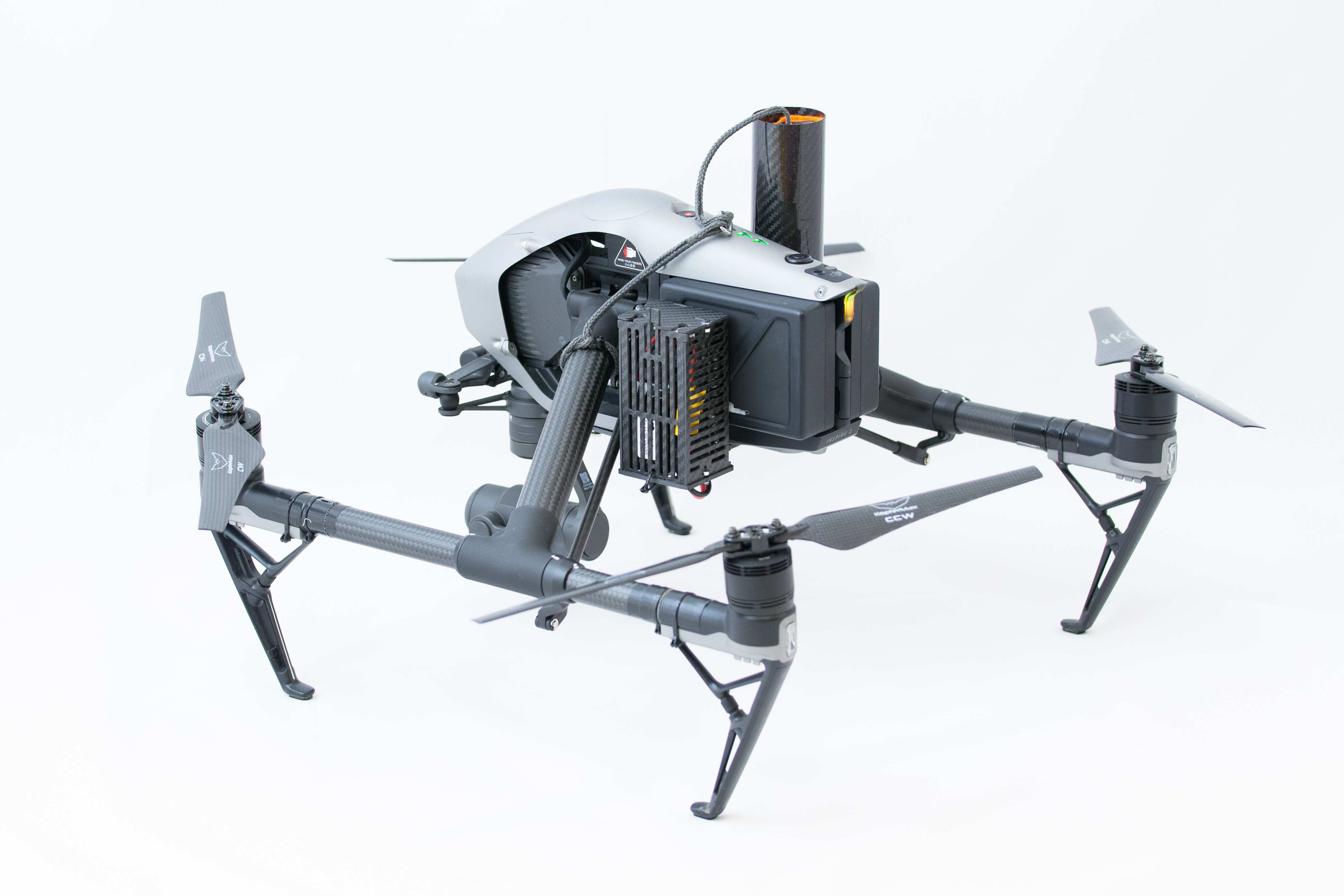
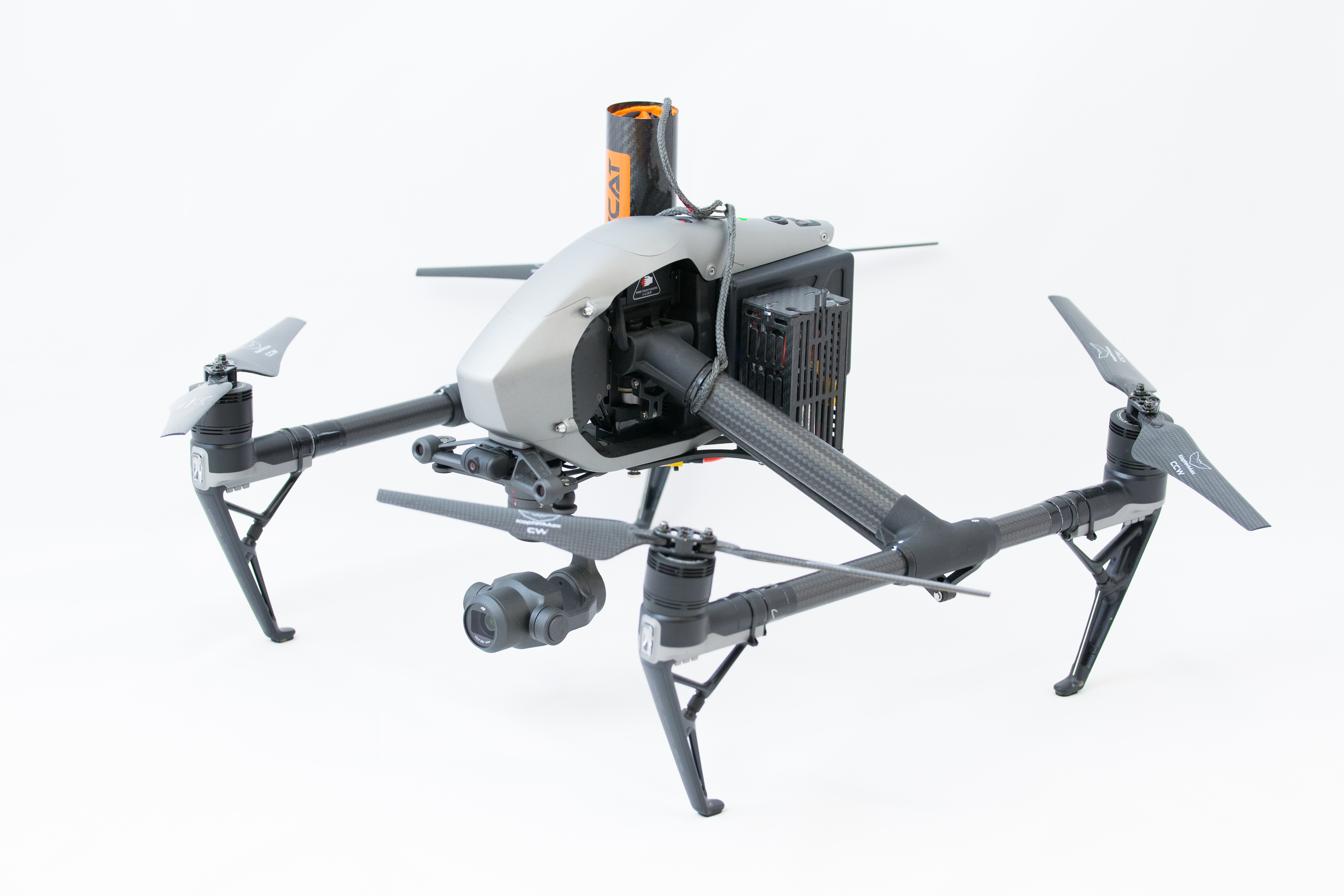
Parachute kit for the DJI Inspire 2 drone.

Features
- Easy to use, one button operation
- Patent pending FUSE technology with spring preload
- Extremely fast deployment
- Immediate motor stop without need of CSC command
- Low descent speed
- Separate independent battery
- Dedicated, encrypted data link on dissimilar frequency from drone controller
- Complete telemetry with battery voltage and fuse health
- Easy to install and reload
- No drone warranty infringement
Technical
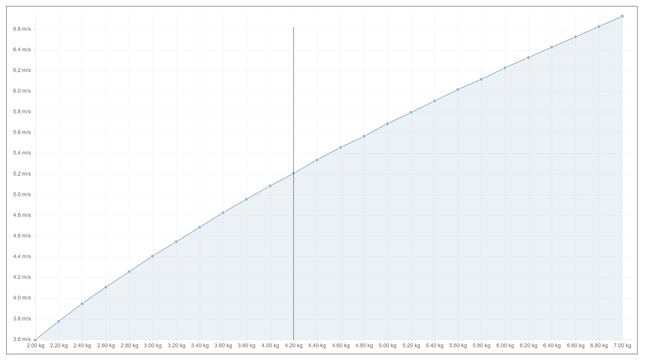
Descent speed vs. UAV weight
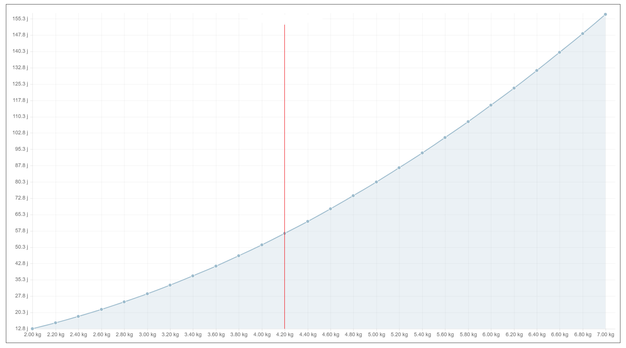
Impact energy vs. UAV weight
Parachute performance
- Diameter: 120cm
- Descent rate: ~5m/s (Inspire 2, X5S camera)
- Impact energy: 58 J
- Equivalent to fall from 1.4m heigth
Datalink
- 433 MHz (EU), 900 MHz (US)
- Dynamic PSK, 256-AES encryption
- (coming soon via SW update) Frequency hopping spread spectrum
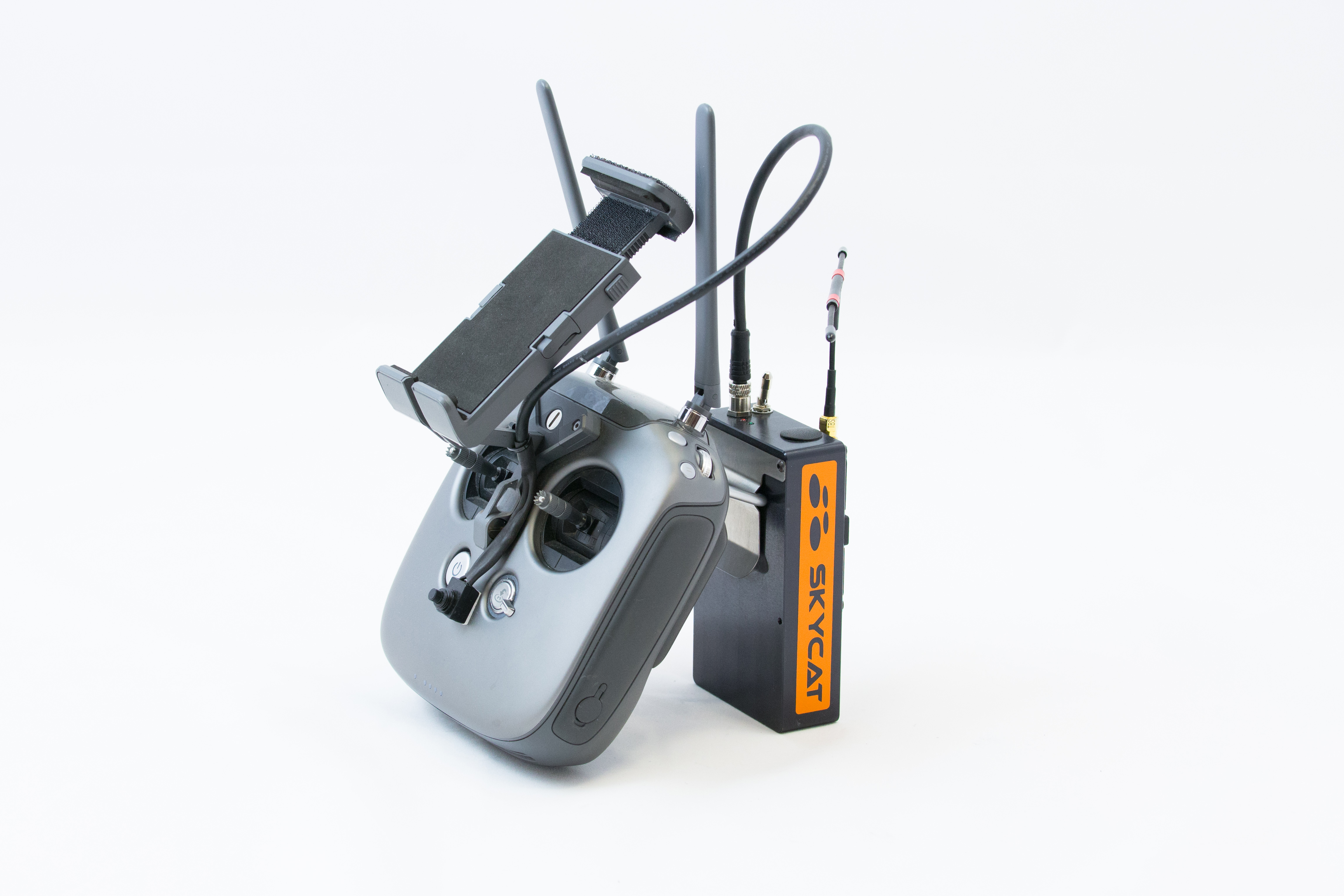
Handheld radio
- Bright graphical OLED display
- 4 buttons for configuration
- USB type C charging port and data transfer
- 1500mAh integrated battery
- 12 hours operation
Airborne unit
- 500gr AUW
- 2s to 6s operation
- 3x configurable 5v standard RC output channels (1 used by motor cutoff)
- 1x TTL 3.3v serial port for future expansion
First installation
The following operations needs to be performed only once, when initially installing the parachute kit to the aircraft, or when transferring the system to another aircraft.
Installing the launcher frame
The launcher is designed to be installed to the “Extended device mounting” bay of Inspire 2.
For more information, please check page 9 in the DJI Inspire 2 manual.
Use the four supplied thumb screws for fastening.
If you feel the need, use only soft threadlock (blue one); do not use hard threadlock (red ones).
Check screw tightness regularly and adjust if necessary.
Follow the video and step instructions below in order to install the parachute kit to the DJI Inspire 2 drone:
VIDEO - Parachute kit installation
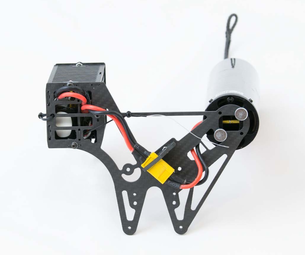
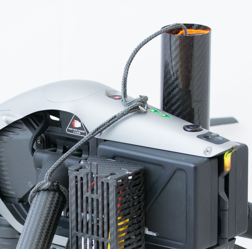
Connect all cables like in the image above, to ensure everything is ready
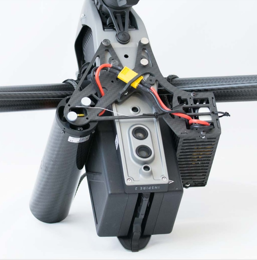
Attach the kit to the bottom by the four included thumb screws
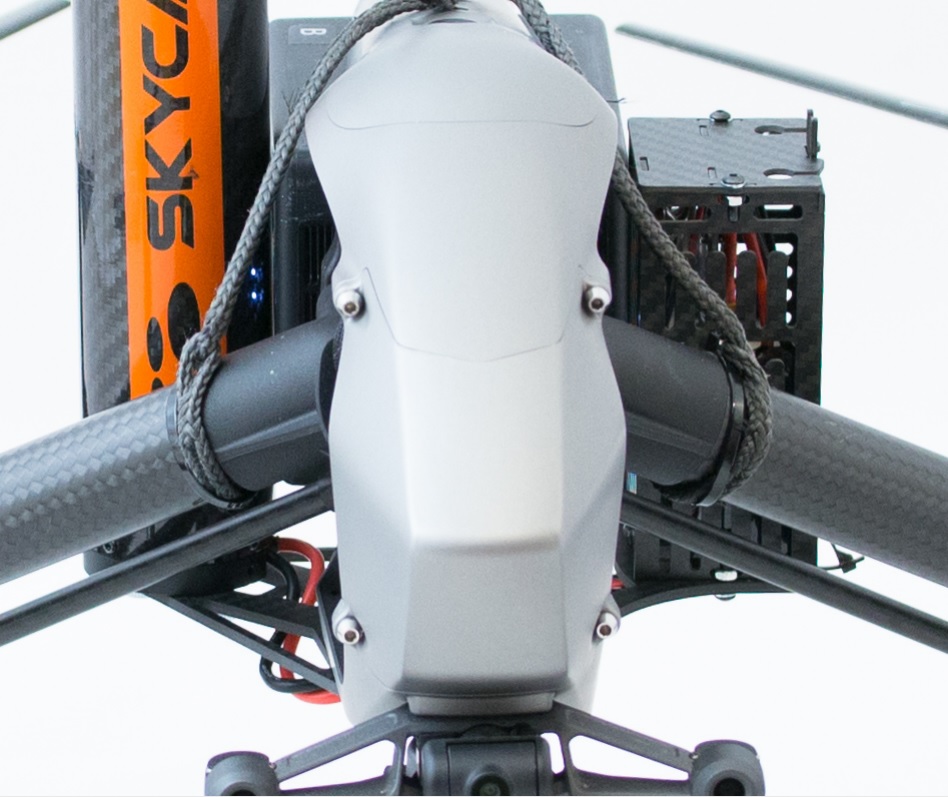
Loop the two ropes around the arms; add zipties to avoid sliding if you feel so
Attach the parachute to te two loops via the included metal shackle
Wiring the motor cutoff unit
The KopterMax motor cutoff is a small circuit board that communicates with drone's motor controllers, and overrides the commands from the FMU to force the motors into an immediate stop.
It is installed into the nosecone of the aircraft with the following procedure, and it intercepts the signals from the flight controller to the ESC wiring.
- Remove the 4 screws from the nose of the drone with an allen key for 2.5mm hex screws
- Remove the metal nosecone
- With regards to the two braided cables coming from the top of the flight control unit, unplug the two connectors from the flight controller
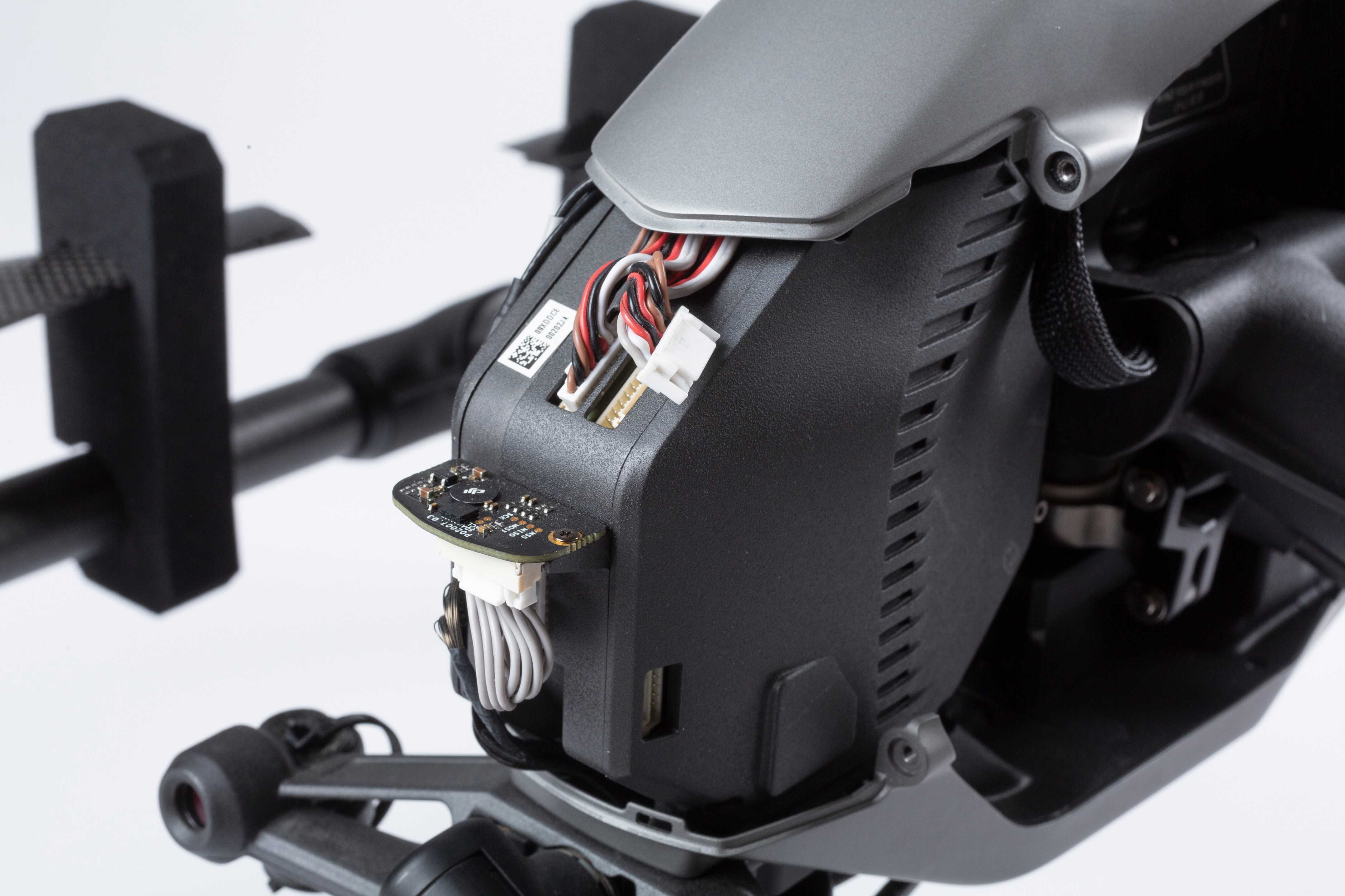
- Plug the wiring from the drone into the cutoff circuit; mind that they have different pin count, so there is no chance of error
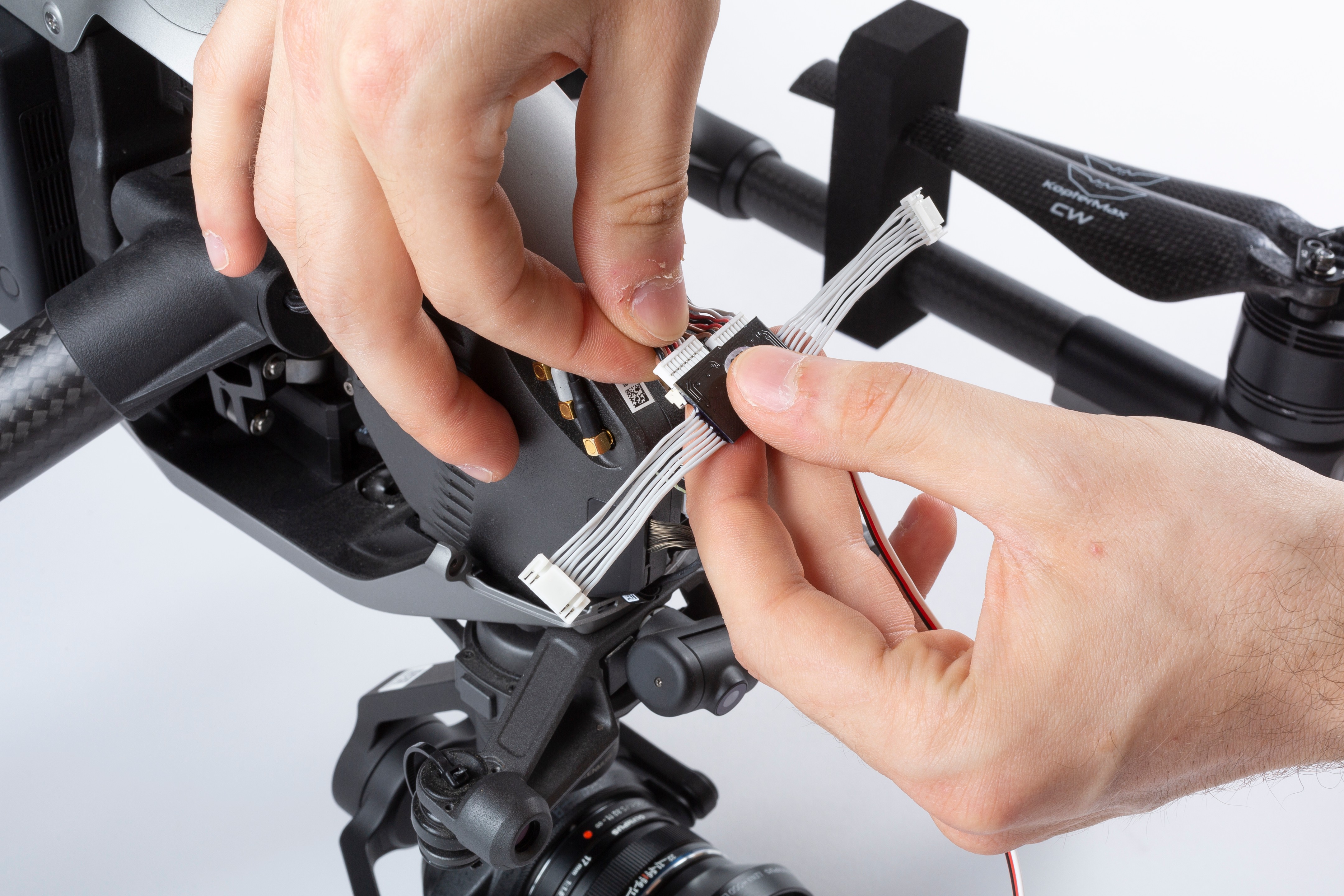
- Plug the KopterMax motor cutoff white cable connectors into the flight control unit; pin count is also different one from the other, so only the correct configuration is possible
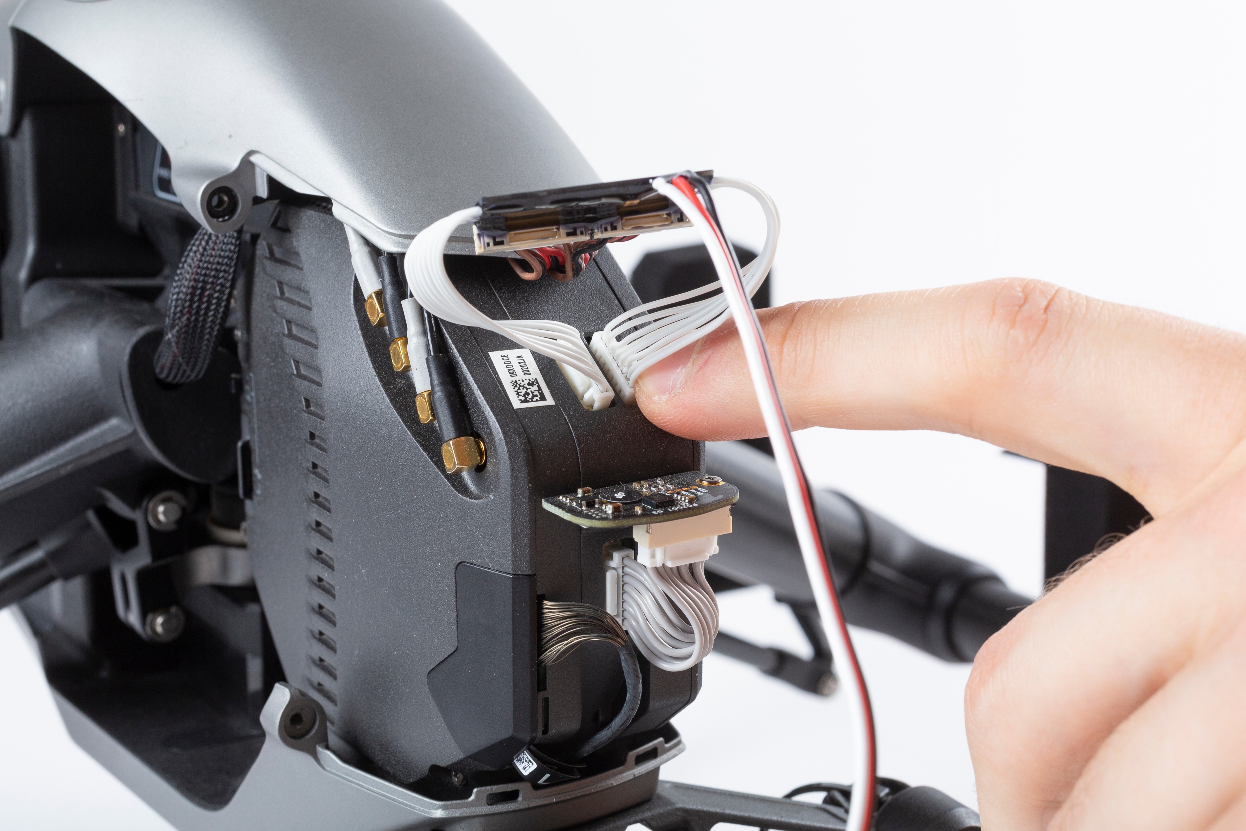
- Route the motor cutoff activation and power cable along the top frame of the drone, checking that it doesn't move and that it doesn't interfere with the arm lifting mechanism
- Reinstall the nosecone paying attention not to pinch any cable or damaging the cutoff device
- Secure the nosecone with the four hex screws
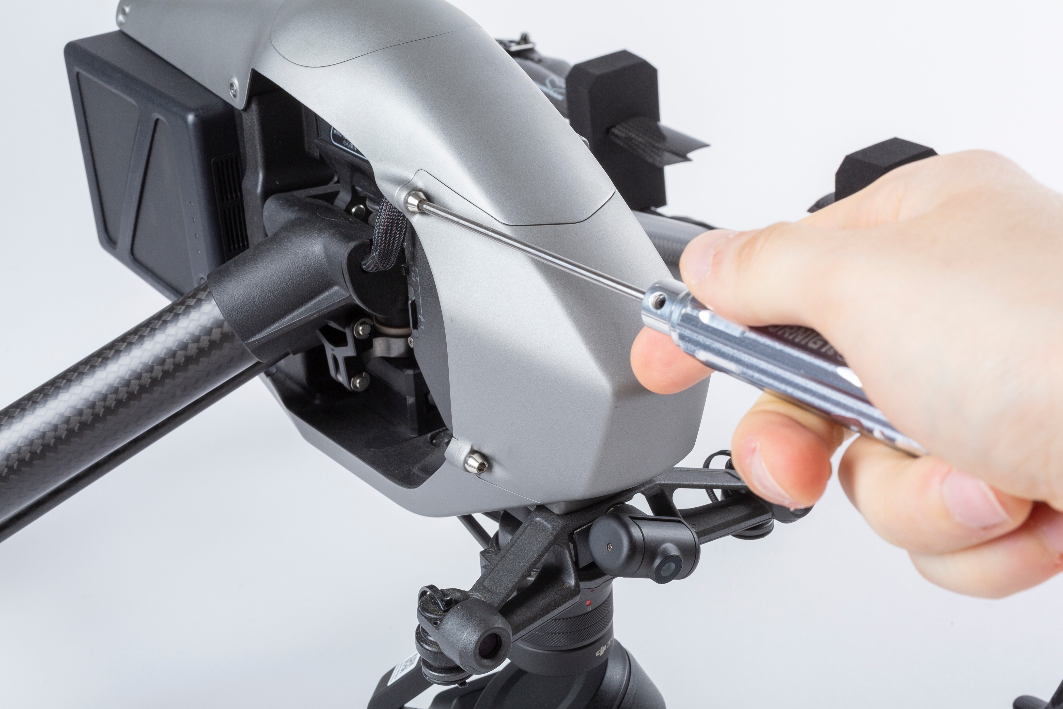
Remove the 4 screws from the nose of the drone with an allen key for 2.5mm hex screws
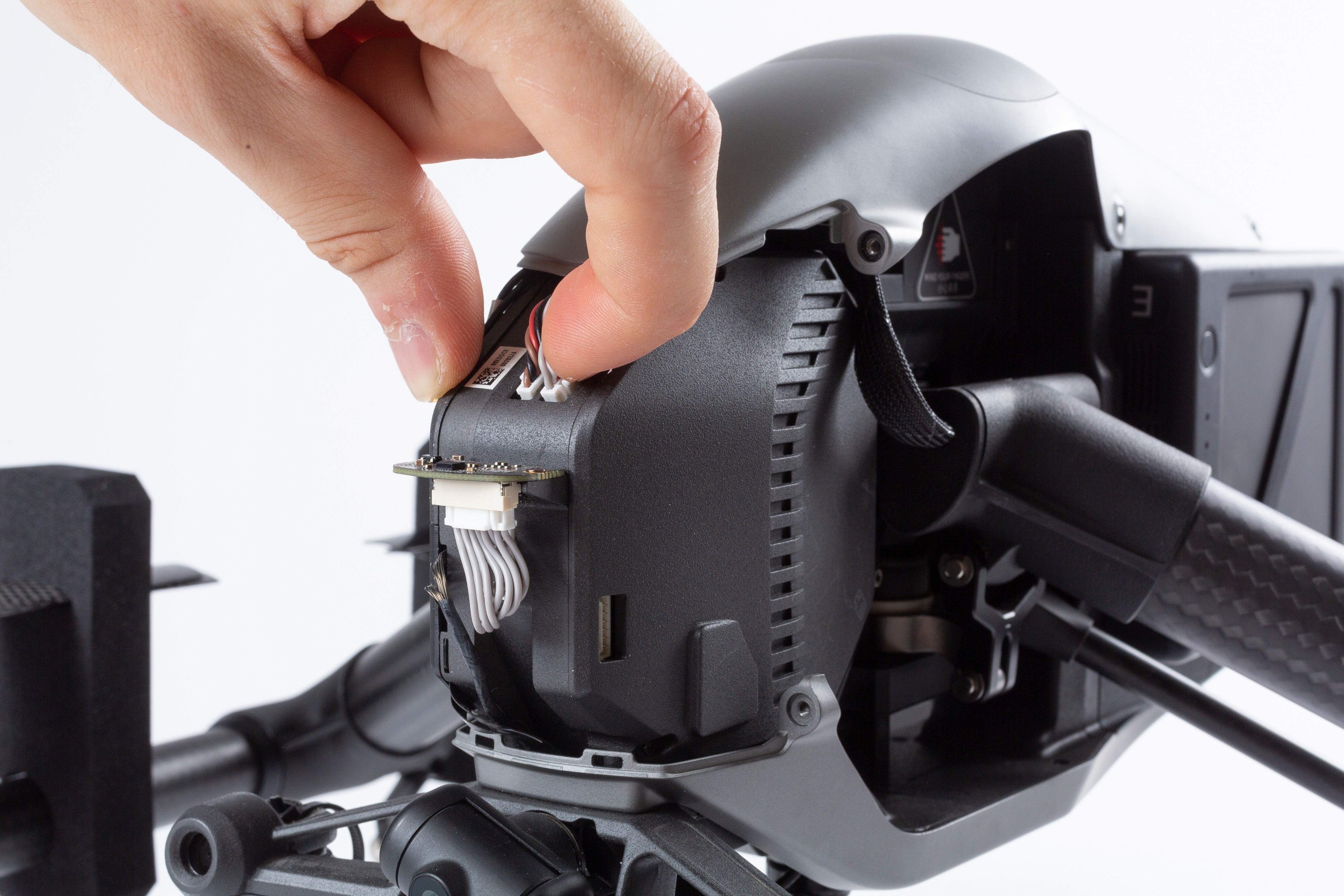
Unplug the two connectors from the flight controller
Unplug the two connectors from the flight controller
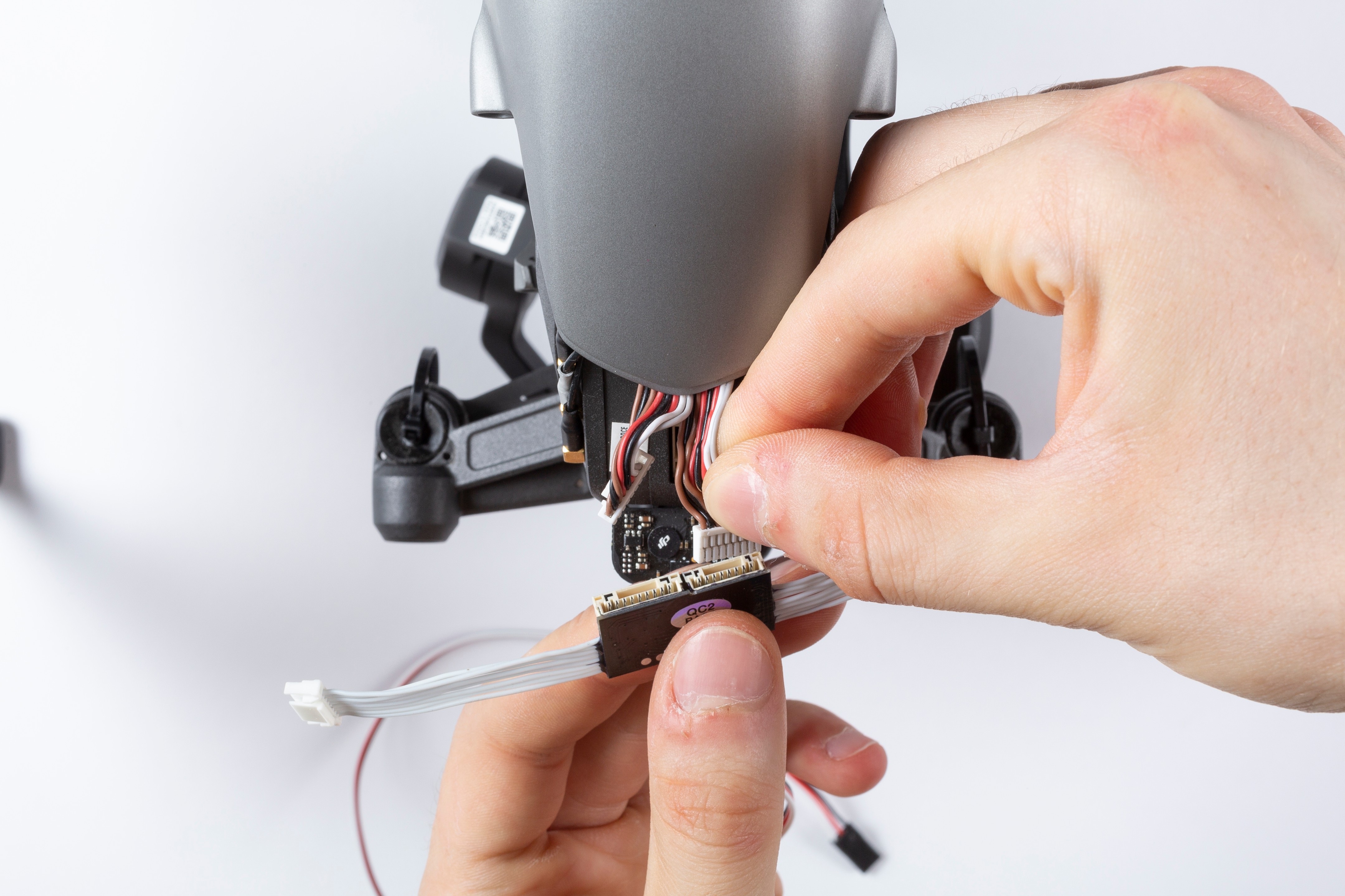
Plug the wiring from the drone into the cutoff circuit
Mind that they have different pin count, so there is no chance of error
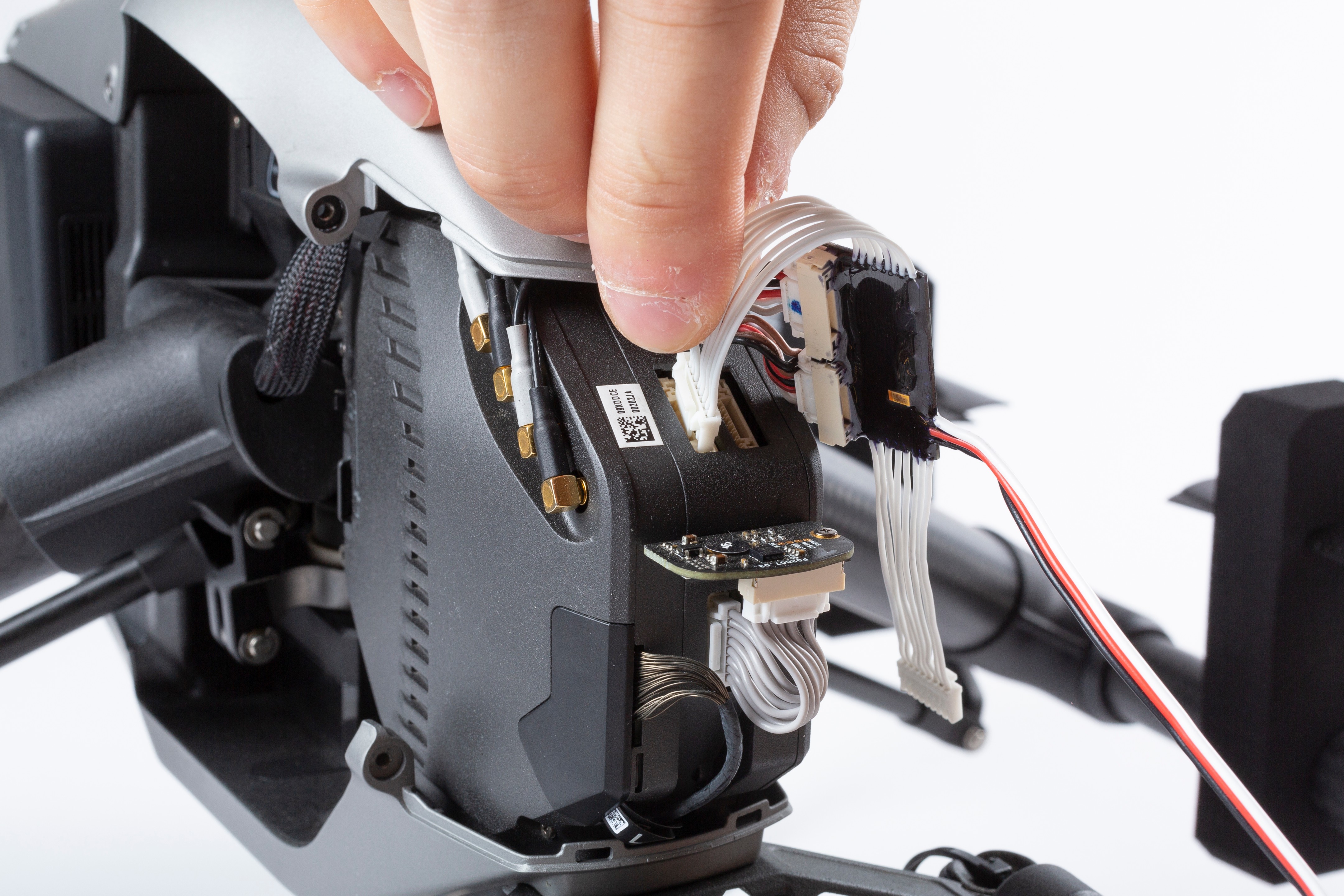
Plug the KopterMax motor cutoff white cable connectors into the flight control unit
Pin count is different one from the other, so only the correct configuration is possible
Reinstall the nosecone paying attention not to pinch any cable or damaging the cutoff device
Secure the nosecone with the four hex screws
Preparing for a flight
Making fuses
Systems comes with some fuses pre-made, and the required material to make more.
IMPORTANT: Do NOT use any other steel wire apart from the one provided by KopterMax!
This wire is strictly respondant to strength and electrical resistance requirements that are very narrow.
Here are the steps for making correct fuses:
- Cut 120mm length of fuse wire. Use only a sharp, steel-rated pincer.
- Insert two locking bits to each fuse end
- Form a loop at each end, like in the picture, and insert the ends into the locking bits
- Crimp the four locking bits firmly, so that the wire is secured and cannot be removed
Pre-loading the launcher
Loading the launcher is a very delicate and dangerous operation; a big and powerful spring is used to eject the parachute, so a lot of energy is tored in the system when it is armed.
- Use of safety goggles is recommended while arming the launcher
- Only use the included plunger to compress the spring; any other item can damage the piston inside the launcher
VIDEO - Preloading the launcher
Parachute folding
It is very important that the parachute itself is folded correctly in order to properly deploy.
- Always fold on a clean and dry surface.
- If launcher stays loaded for over two months, this can decrease deployment throw distance in an emergency
It is very recommended to refold the parachute periodically.
- Follow the steps in the video below to perform a correct and safe folding of the chute fabric:
VIDEO - Parachute folding tutorial - Wrap parachute cloth around the parachute so that black side faces out.
- Insert the folded and wrapped parachute into the launcher tube, paying attention that the rope attaching to the drone is not impeeding the deployment
Make sure ropes do not interfere with propellers!
Do not swing loaded launcher around. G-forces can slide the parachute out accidentally!
System setup
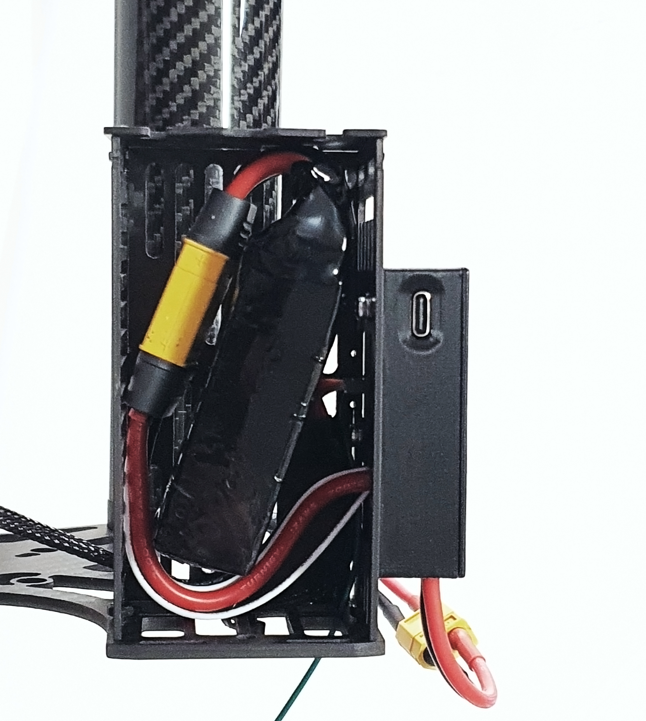
Connect the battery to the air unit as per pictures below.
- Connect the provided battery to the connector inside the carbon fiber box
- For older versions of the kit only: always connect both cell balancing connector and main power connector from the battery!
- Install the battery into the carbon fiber box and close the lid
Pre-flight checks
Before taking off for a flight, ensure the following checklist is completed in order to avoid misfiring, failures or unattended activations.
- Inspect all components for damages or loose screws/parts
- Before connecting the trigger, check that system is not armed (status on display must be “CHECK FUSE”, not "KILL" or "ARMED")
- Ensure trigger is connected and detected by the launcher controller unit (display indication must be “FLY”)
- Make sure the parachute cord is secured to the harness and to the aircraft properly
- Check that battery compartment lid is securely closed
- Watch the display for any error detected or any blinking value, indicating a warning condition
Operating the system
We recommend launching the parachute a few times as an exercise, before using it in-flight.
- Do not launch on grass, sand, or other loose material. Airflow generated by the piston can suck debris into the launcher.
- Do not touch the fuse immediately after launch, it can remain hot for a while.
Arming the system
When radio is turned on, it defaults to a normal flight condition; this is indicated by the FLY label on the display (unless specific errors are notified, see the relative section).
To prepare for flight, arming is required. This is done from the main manu, by keeping the “ARM” button pressed for about three seconds.
Visual indicator of arming in progress will be displayed as in the pictures below.
PICS MISSING
Display will switch to ARMED and the KILL button will blink orange.
Parachute is now engaged and on standby, ready for quick deployment.
ATTENTION!!
From now on, the system is ARMED! A single click on “KILL” button will stop the motors and activate the parachute immediately!
Always handle the activation radio with extreme care while it is armed!
To disarm the system, keep the "ARM" button pressed for about three seconds, and the disarming countdown will start, similarly to the arming sequence.
Terminating the flight
Pressing the red KILL button while in ARMED mode will immediately stop the motors and deploy the parachute.
KILL button will blink red, and display will show the KILL symbol.
From this point, recovery of the drone is no longer possible via its own power.
Do NOT disarm the system for any reason until you recover the drone AND you make sure that the flight control is not commanding the motors to spin.
We recommend immediately removing power from the drone after it is collected in case of a parachute controlled or crash landing.
Best practice
Things to do
WIP
Things not to do
WIP
Maintenance
Every flight
- Check that the fuse is correctly installed
- Make sure the launcher power cable is connected to the electronics box
- Test propeller clearance by turning them by hand and ensuring they not interfere with parts or wires
- Ensure there are no errors or warnings (hint: no blinking symbols/text should appear on the radio display)
- Check the battery levels are correctly reported (use the STATS menu)
- Check that battery is not bulging or swollen
After deployment
- Carefully inspect all the mechanical components for damages due to crash landing or launcher activation.
The spring in the parachute launcher is so powerful that it may occasionally damage the launcher or mounting hardware. - Remember to remove the blown fuse from the launcher tube. Pay attention that now the fuse is split in half and there will be two pieces of steel wire to remove, one at the bottom and one at the top of the tube.
- Check the parachute for tears, holes or broken ropes.
- Check that the ropes securing to the aircraft frame are still solid, and that no damages have been caused to the drone frame.
Every 20 flights
- Check that the cells in the battery are still well balanced (voltage difference under 0.2v at any state of charge)
- Remove and repack the parachute to avoid permanent damage to the fabric
Replacement parts
You can purchase spare fuses, batteries and chargers by contacting KopterMax directly, or one of our worldwide distributors.
Fuses
Due to the delicate nature of the component, use of KopterMax-provided fuses or fuse material is mandatory.
We cannot guarantee safe operation of the device with any other fuse.
Batteries
If for some reason you can't use original KopterMax batteries to power the parachute kit, you can use any standard 3s battery that can give 60 A peak for 10 seconds or more.
The connector pair used on the parachute kit is an Amass XT90I with the following pinout at the battery:
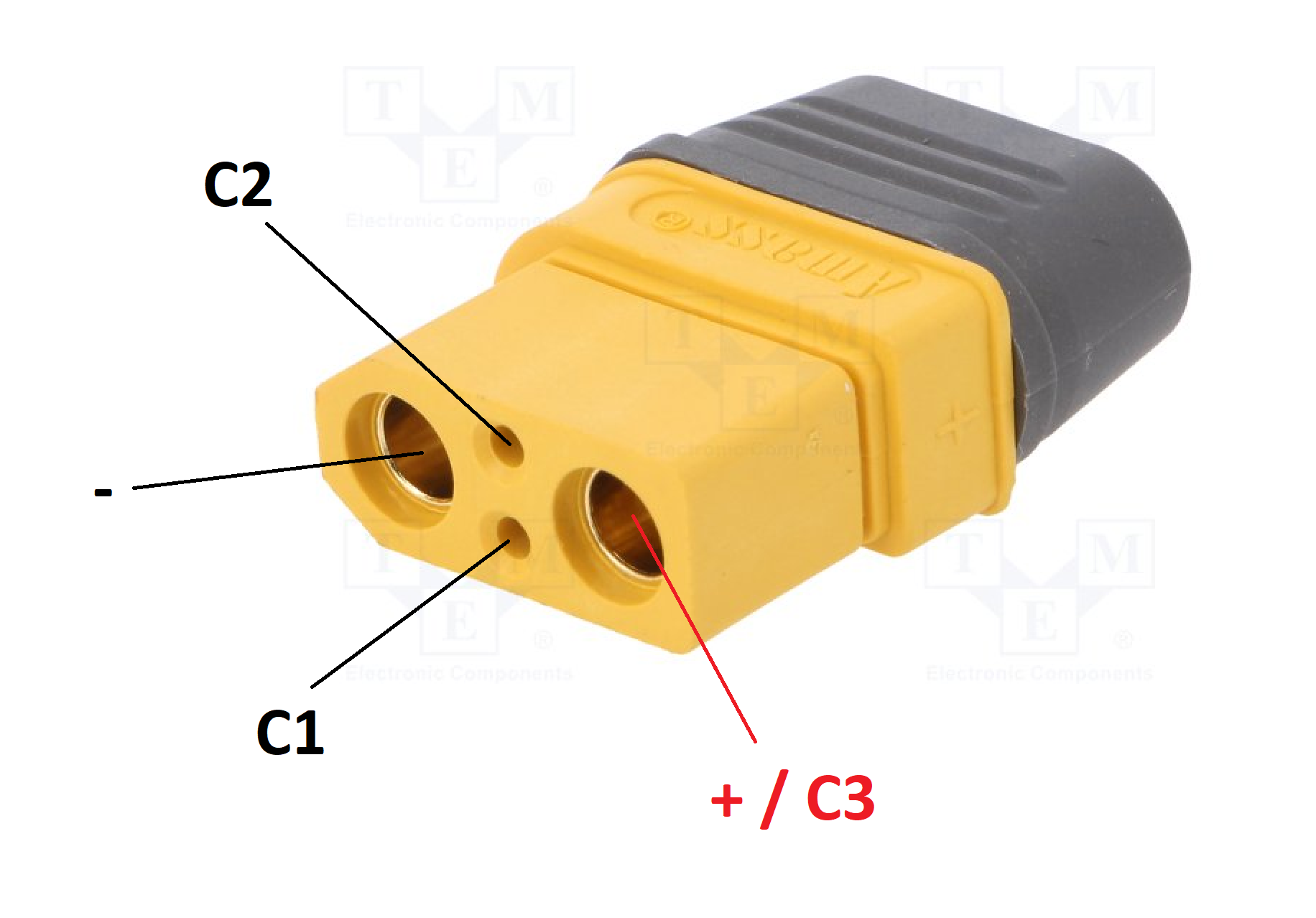
We do NOT recommend tampering with high power batteries if you are not fully confident.
Severe risk of violent fire and explosion exists if any battery wire shorts out!
Regulamentation compliance
This kit has been developed with features relevant for the SORA process for risk mitigation as per EASA UAS regulamentation (see the JARUS guidelines).
Those that follow are technical details of the system that will help in the application for safe operations; specifically, the points we target are from the Means of Compliance with Light-UAS.2511 final version.
Adaptation of the following documentation for compliance with other national aviation authorities should be an easy process.
System overview
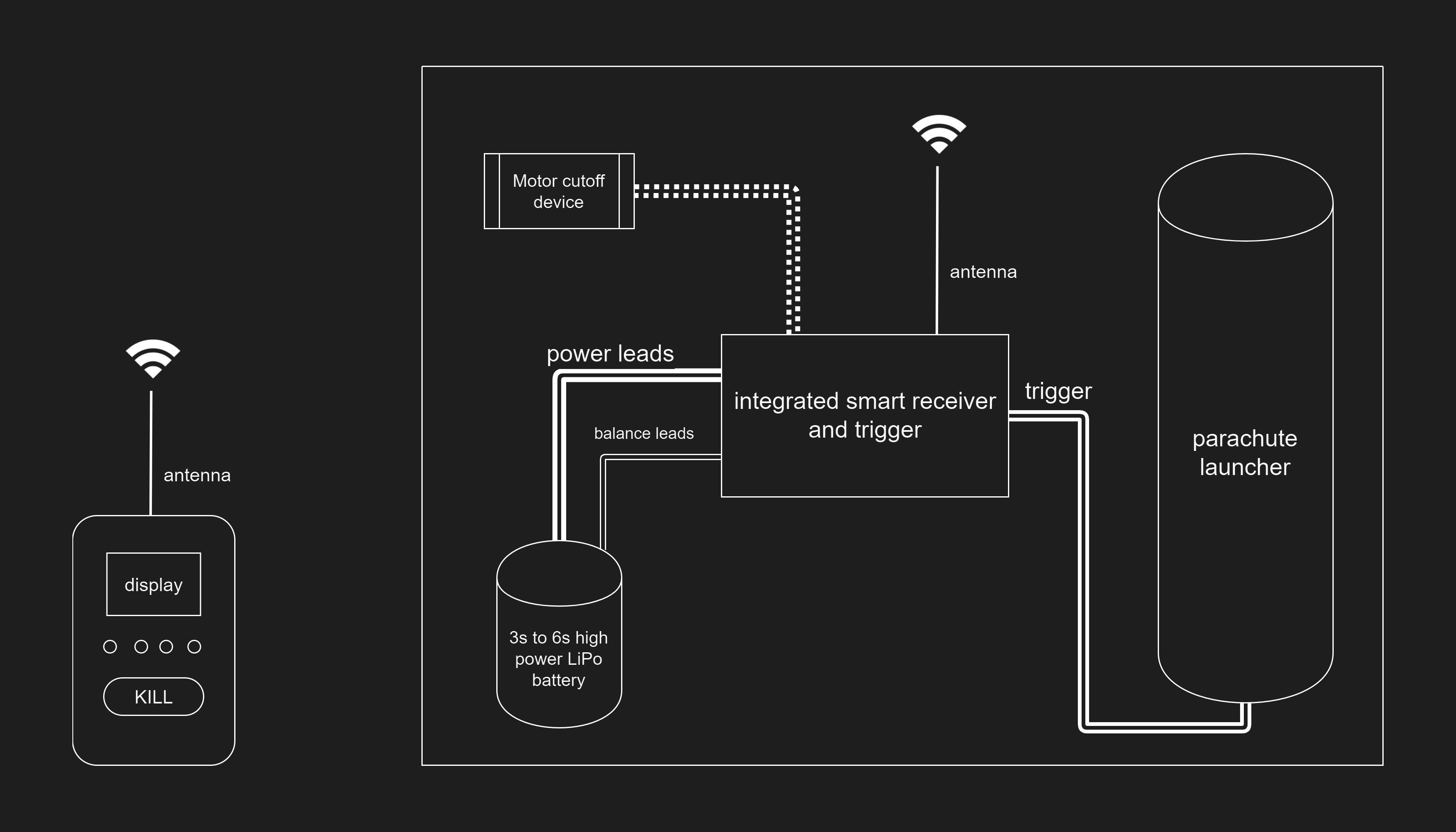
System operation
In ARMED mode, when KILL button is pressed and flight termination is invoked, the motor cutoff will immediately stop and brake the motors.
This will happen in whatever flight mode the drone is (Position, Attitude, Sport or automatic mission), and no CSC manoeuvre will be necessary.
At the same time, the retaining fuse on the parachute launcher will be burnt and an immediate deployment will happen under the power of the spring in the launcher.
Note that a minimum of 15 meters of altitude is lost while deploying the system, so the effectiveness of the parachute at low flight levels is reduced.
Power to the drone is maintained during parachute descent, so all the primary and auxiliary functions of the aircraft apart from flight control will keep operating.
Telemetry, video link and gimbal control will work, provided that there are no electrical failures on the aircraft electronics and main C2 radio link is not disturbed.
Note that parachute will be deployed even if a complete power or radio failure happens on the drone, as the system has a separate battery and radio channel on a dissimilar frequency.
Segregation from aircraft systems
The parachute kit is a fully independent system, intrinsically capable of safe operation without external resources.
Design features and technical elements are embedded in the air unit in order to ensure complete robustness against any possible failure of UAV components.
Autonomous power supply
The air unit is powered by a dedicated battery, that provides power for the electronics, radio link and parachute deployment mechanism.
A 3s to 6s LiPo battery is required, with a minimum capacity of 1000mAh, and capable of a peak discharge current over 60 A.
Single battery cells are monitored for low voltage and unbalance.
Dissimilar FTS frequency
The FTS operates on 433MHz (EU) or 900MHz (US and CA), that is a different frequency band from the main drone command and control link (2.4GHz and 5.8GHz for the DJI Inspire 2).
Any interference on the CC bands, that can cause a loss of control of the aircraft, will not affect the FTS communication, so emergency flight termination and parachute deployment can be performed in any case.
Robustness and operator error prevention
Other than the operation manual and maintenance guidelines as per previous chapters, several automatic failsafe checks and interlocks are in place to reduce the risk of an incorrect behaviour from the user while preparing and operating the system, or for external factors to influcence the safety of the system.
Battery levels
The display on the ground unit has two separate indicators, showing the levels of both the ground unit battery itself, and the air unit one.
A visual alarm is triggered when the levels reach a mid-low point, before the energy left is not enough to continue a safe operation.
The air unit battery level indicator takes into consideration multiple factors:
- total voltage at the main power leads
- absence of main power lead connection
- single voltages of the cells in the pack
- level of unbalance of the cell pack
This ensures that each cell is separately monitored, as the usual way of monitoring total pack voltage does not recognize cell unbalance.
In LiPo packs cells are not perfectly identical, and if one is slightly weaker than others, an unbalance happens over time and cycles, resulting in sudden pack voltage drops and loss in power, that may not be identified with sufficient forewarning.
An algorithm is also implemented that automatically checks if the battery connected at power-on is balanced, or if some cells are broken.
Since low temperature negatively affects performance of lithium batteries, a temperature sensor is embedded in both the air and groung unit, warning the operator if the weather conditions are outside of operating window of the batteries.
Radio link
Two radio signal quality indicators give a simple information on the reliability of the link between ground and air unit.
Several external factors can influence the radio reliability and performance, and despite a solution is not always possible, systems are implemented in order to mitigate the effects or at least warn the operator:
- excessive distance: a progressive reduction in received signal strength and consequently diminishing signal quality is reported, with visual alarm occurring below a safety threshold
- external interferences: frequency hopping is active, so single channel interference does not disrupt the communication
- crosstalk: every unit is locked to a single transmitter with a pairing process that automatically generates random encryption keys and frequency hopping sequence, so no crosstalk is possible amongst similar systems
- eavesdropping and hijacking: radio link is encrypted with a strong scheme and private key, so listening on the communication is not possible, let alone sending malicious commands to the unit
Parachute trigger health
The parachute kit uses a peculiar and patent-pending activation system; once triggered, a steel wire is burnt by high current flow, releasing the parachute by a spring-powered expulsion device.
Several benefits lead us to opt for this solution:
- no mechanical/motorized parts: no gears or motors are used, reducing the complexity of the system and number of points of failure; zero mainteniance is required.
- safe to transport: no pyro or gas activated systems are used, so the system is safer and easier to transport even via airplane cargo.
This system requires a steel fuse to be put in place before flights; to avoid the possibility of flights initiated without a fuse installed or with an improperly connected one, some safety check are performed by the electronic and software:
- fuse presence: if the fuse is not installed, a visual indicator will warn the operator
- fuse health: proper connection and quality of the fuse is checked at all times, even during flight, by intelligent and non disruptive probing
- fuse burn and current monitoring: upon activation, a current sensor checks if the fuse burned correctly, allowing to get a feedback on actual parachute deployment, useful when operating at BVLOS