A/B failover switch, 12 channels (compact)
The compact version of the KopterMax A/B failover switch. It provides the same 12 RC channels switching capability between two banks, with software-generated channels, in a smaller form factor. The main differences from the standard version are the use of solder bridges instead of jumper pins for channel configuration, and the absence of the selectable power routing feature on the output rail.
Specifications
- 12 output channels
- < 1mS activation delay
- 2 input banks (A/B), 12 channels each
- 3 groups of 4 channels, capable of per-group A/B switching
- 12 independent software-generated and user configurable channels
- per-group independent output frequency ( 50Hz / 400 Hz )
- per-channel selectable “bank B” function (bank B inputs, or software-generated)
- user-selectable active-high or active-low trigger input, with adjustable intervention point
- 5-way input redundancy
- expansion port for future use
- USB type-C communication for configuration and software updates
Setup and configuration
Connections
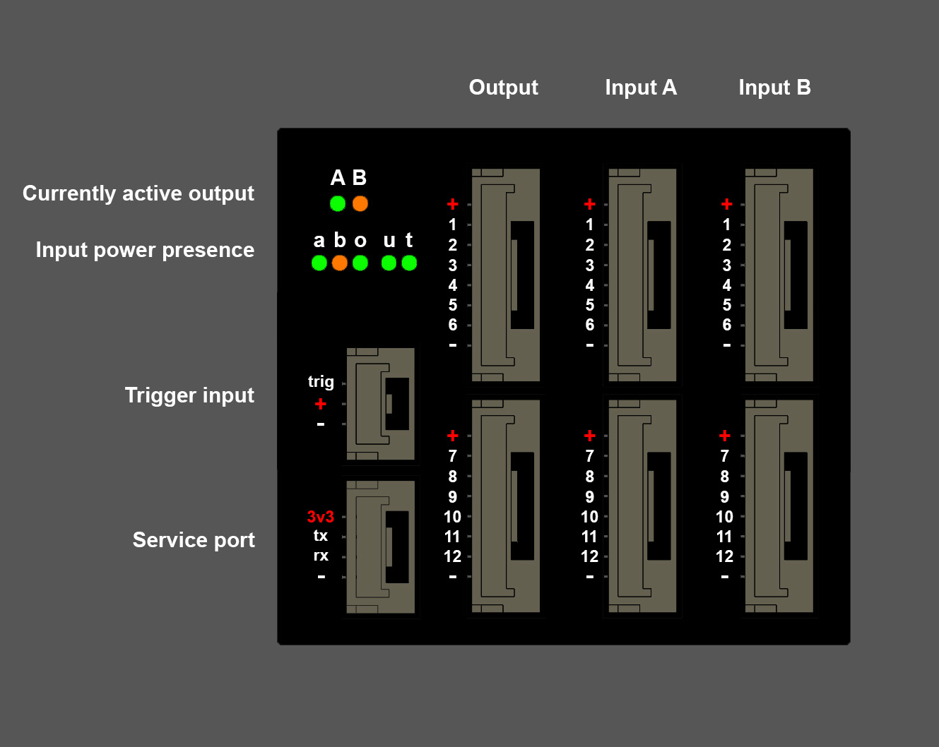
In order to utilize the device, connect input channels to banks A and B.
Default output signal is from bank A; it is possible to change this preference with the configurator software.
Connect any 1mS - 2mS signal to the trigger input; default activation (switch to bank B) happens at 1600uS input, and deactivation (back to bank A) occurs at 1400uS.
Two different colour LEDs will indicate if either bank A (green) or bank B (orange) is active.
If groups are configured to be active independently, even one single active group in a bank will cause the relative bank LED to light up.
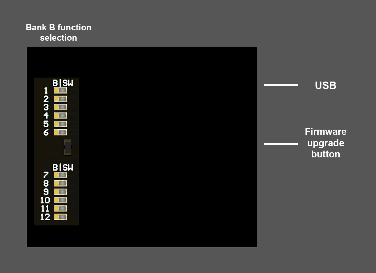
To use software-generated failover signals with user-defined values, a solder bridge needs to be placed between central pad and “SW” on the back of the board, per each channel desired.
To use bank B inputs as failover signals, the solder bridge has to be placed between central pad and “B”.
Power presence is indicated by the A-B-O-U-T LEDs, indicating respectively bank A, bank B, output, USB and Trigger.
Note that just one power source is enough for the correct operation of the cutoff device.
If multiple power inputs are connected, the highest voltage one will effectively power the device.
Configurator software
The KopterMax configurator software can be used for all the KopterMax products.
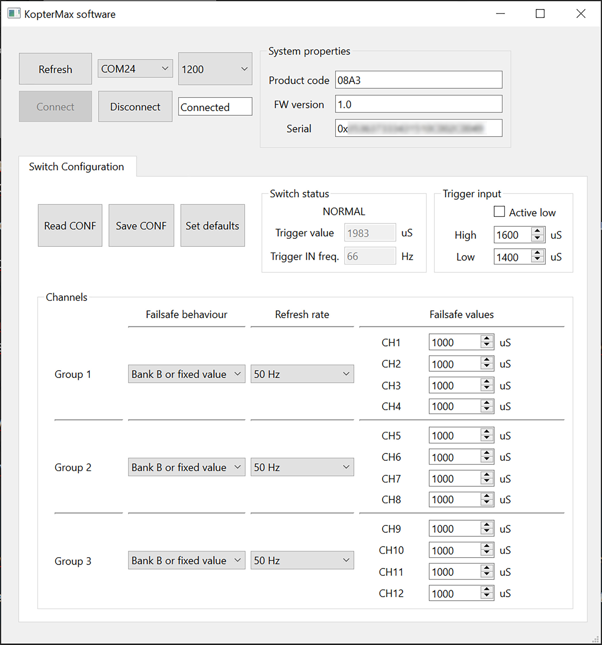
First of all, after connecting the failover switch to a USB port on your PC, find the corresponding COM port in the list.
Clicking “Connect” will identify the device automatically, and populate the software with all the parameters from the device.
To save any modified parameters, click “Save CONF”; in the same fashion, to refresh the window with the parameters saved in the device, press “Read CONF”.
You can revert back to the default options with “Set defaults”.
In the “Switch status” panel, NORMAL/FAILOVER will indicate if the device is triggered, and just below, the realtime trigger input value and PPM frequency.
Under “Trigger input”, you can set if the device is activated by high or low pulse values, and the precise value that will trigger the activation/deactivation.
The remaining area allows you to configure per-bank output behaviour, and value/refresh rate of each software-generated channel.
Remember that in order to use software-generated outputs on a channel, you need to place a jumper between rows “S” and “SW” of that channel on bank B; otherwise, external input on bank B will be used.
ATTENTION!!
Always remember to click “Save CONF” after you edit any parameter, and to TEST that the modification you made actually works as intended!
Technical details
- 12 RC channels with PWM 1000-2000uS nominal range
- 5v to 15v input voltage on all rails
- 5-way redundant power inputs
- 3.3v signal I/O, 5v tolerant
- 32bit 60 MHz advanced signal processor
- USB type-C